Ditching the Perfboard: Why Mill Your Own PCB?
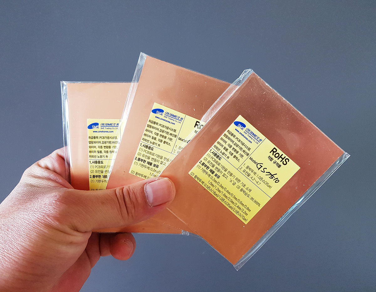
When you need clean signal processing, a perfboard covered in messy jumper wires just won’t cut it. Chemical etching is an option, but it’s messy and toxic. As a CNC guy, direct milling (isolation routing) on a homemade machine is the most logical choice. However, I had no intention of learning dedicated PCB design software (EDA tools like KiCad or Eagle) just for a one-off project. I simply sketched the circuit in my everyday mechanical CAD tool and grabbed three 100x75mm single-sided epoxy copper boards (FR4). Efficiency is everything.
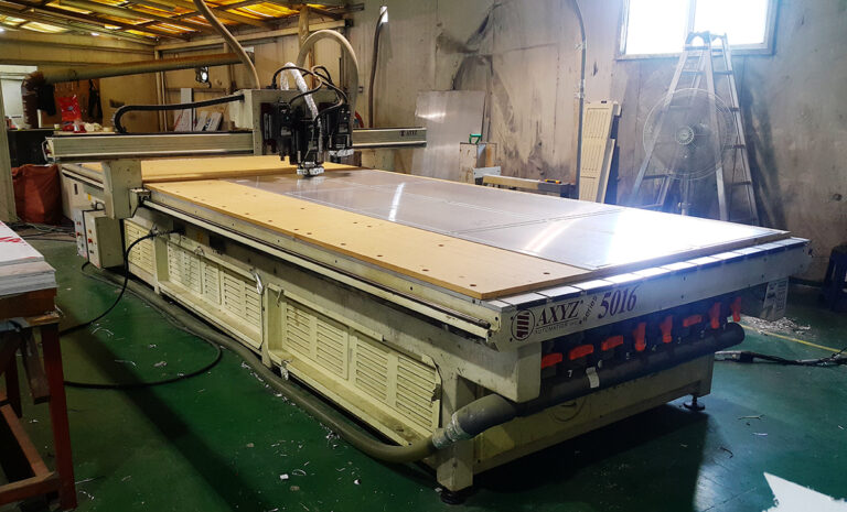
Feeds and Speeds: Finding the Sweet Spot for a Belt-Driven Spindle
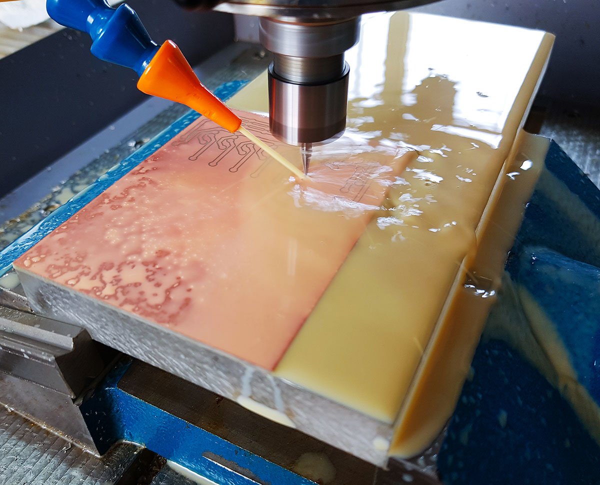
At the time of this project, my homemade CNC was equipped with a belt-driven servo motor, specifically chosen for the torque needed to mill steel. Because it lacked the insanely high RPMs of a modern high-frequency spindle, my feeds and speeds had to be conservative. For the isolation routing, I used a cheap 0.4mm 20-degree V-bit (3.175mm shank) running at 6000 RPM with a feed rate of 160 mm/min.
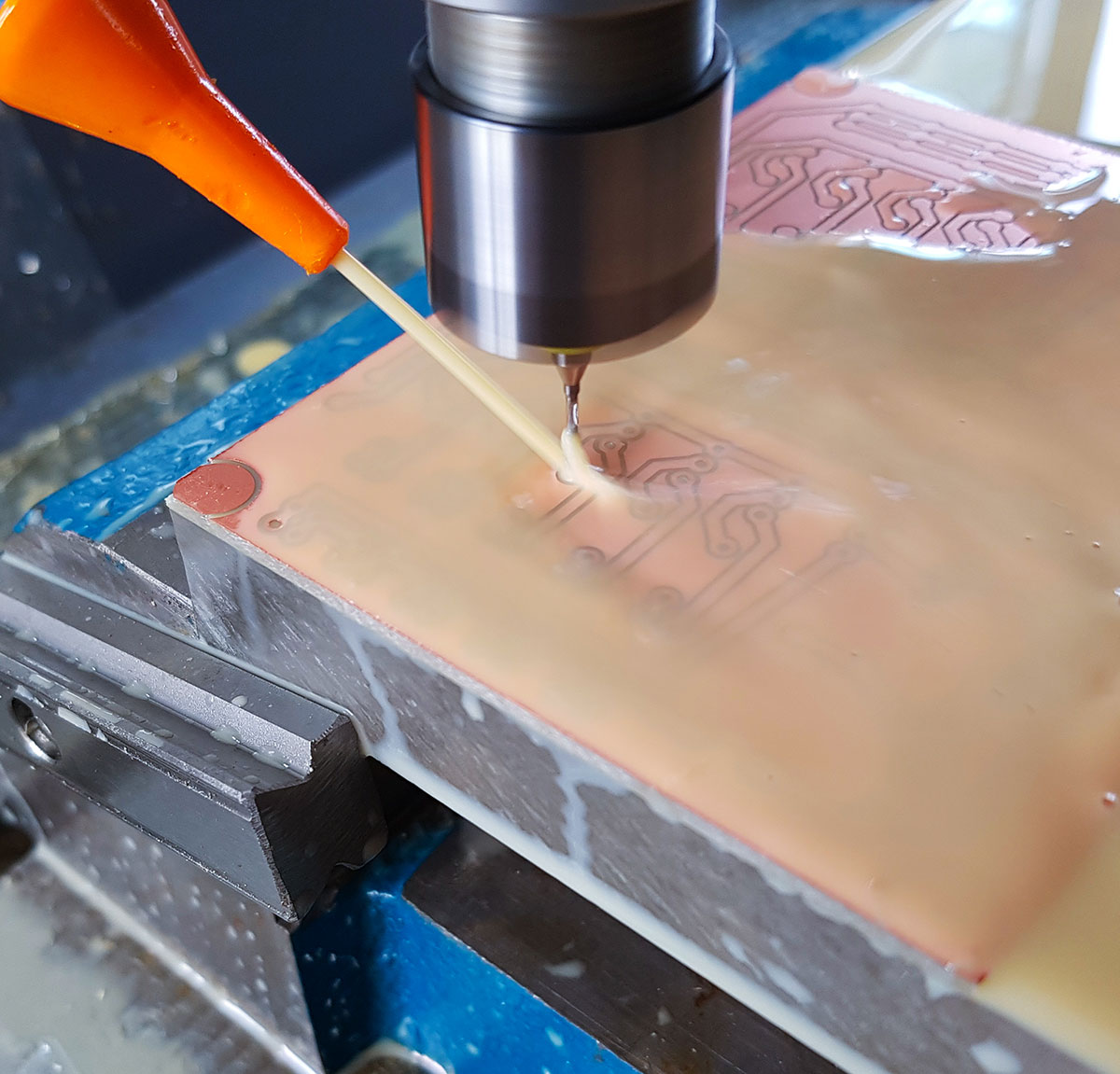
For drilling the through-holes, I switched to a 1mm carbide drill bit, maintaining 6000 RPM but dropping the feed to a safe 50 mm/min. These aren’t universal standards by any means, but they were the reliable sweet spots I found for my custom setup to avoid breaking bits.
The Z-Axis Reality Check and a 2-Up Array Design
In PCB milling, a 0.1mm variation in Z-height is the difference between a clean circuit and a destroyed board. I learned this the hard way by using a scrap piece of acrylic as my baseboard. Its uneven thickness resulted in deeper cuts on one side of the board.
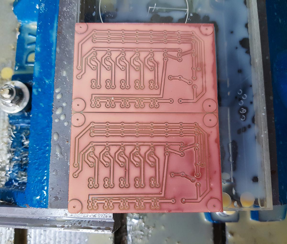
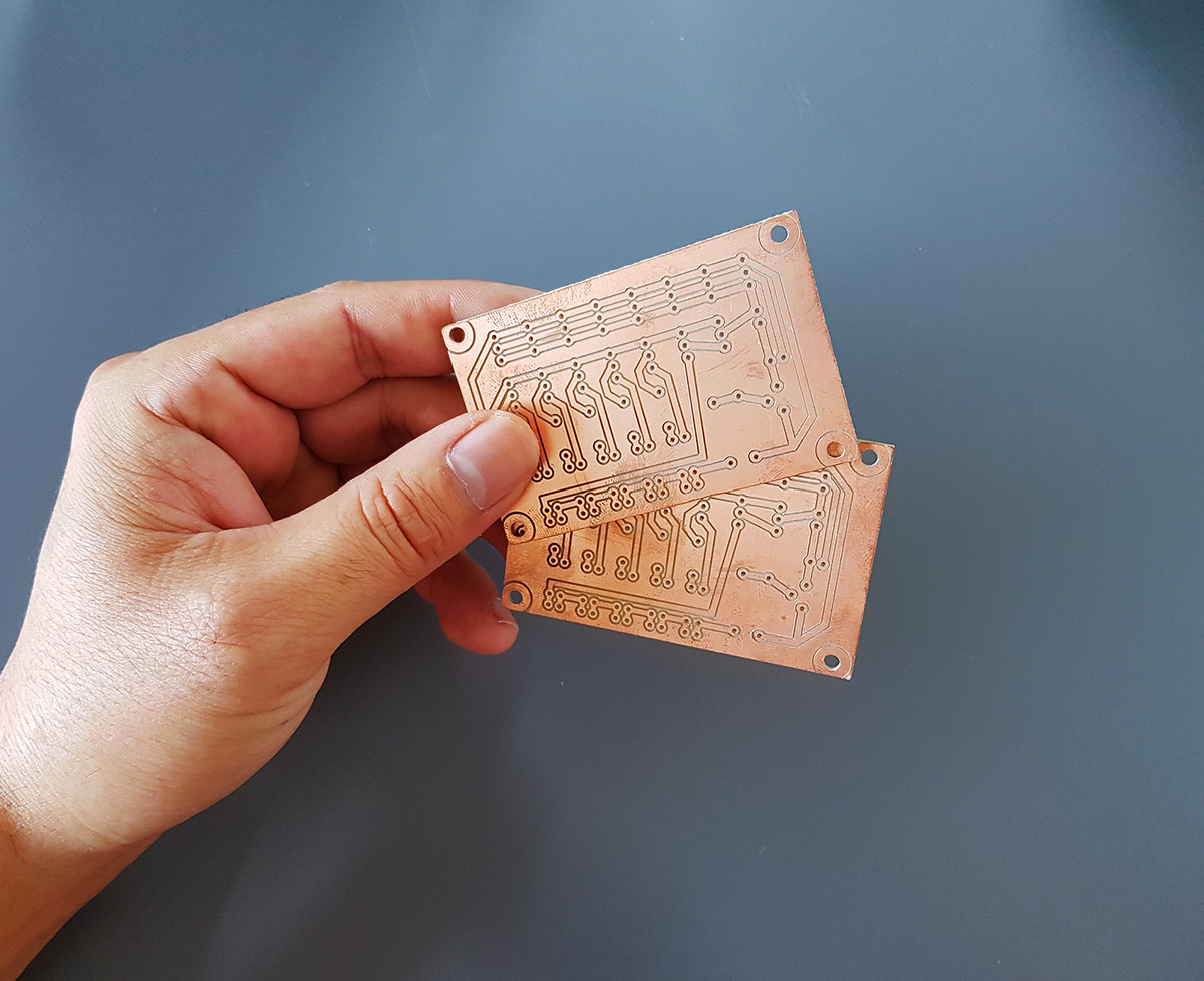
It’s a painful lesson in bed leveling, but there were no shorts or broken traces. To maximize the 100x75mm board, I had originally designed the circuit as a 2-up array (panelized). After drilling the mounting holes, I simply cut down the middle to separate them. One half goes to the current project, and the other goes straight into the parts bin as a spare. If it works, it works.
Soldering and Assembly: An Honest Day’s Work
I’m no soldering master, but I gave it my best effort.
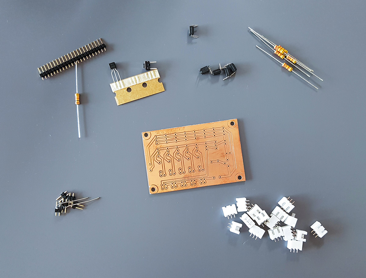
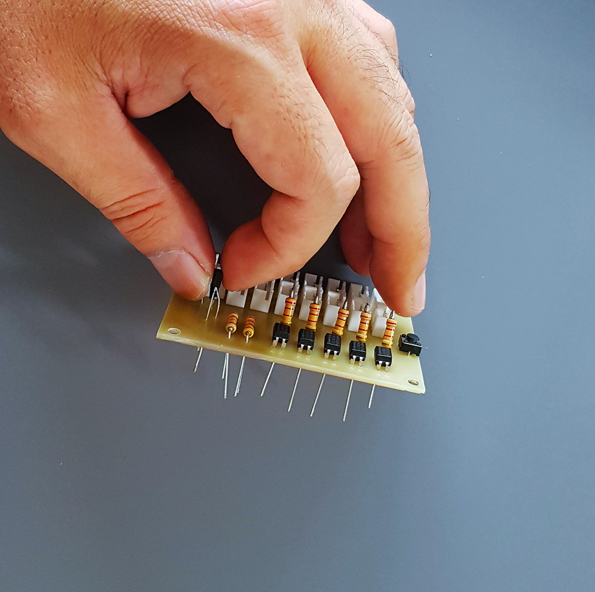
I populated the components and went to work with Kester 0.8mm solder wire and my trusty Chinese temperature-controlled iron.
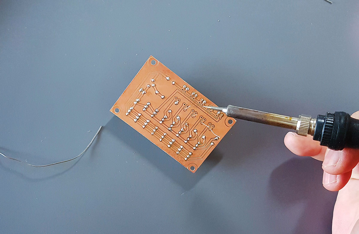
If you are curious about the entire workflow—from the initial CNC milling to the final hand-soldering—check out the quick video log below.
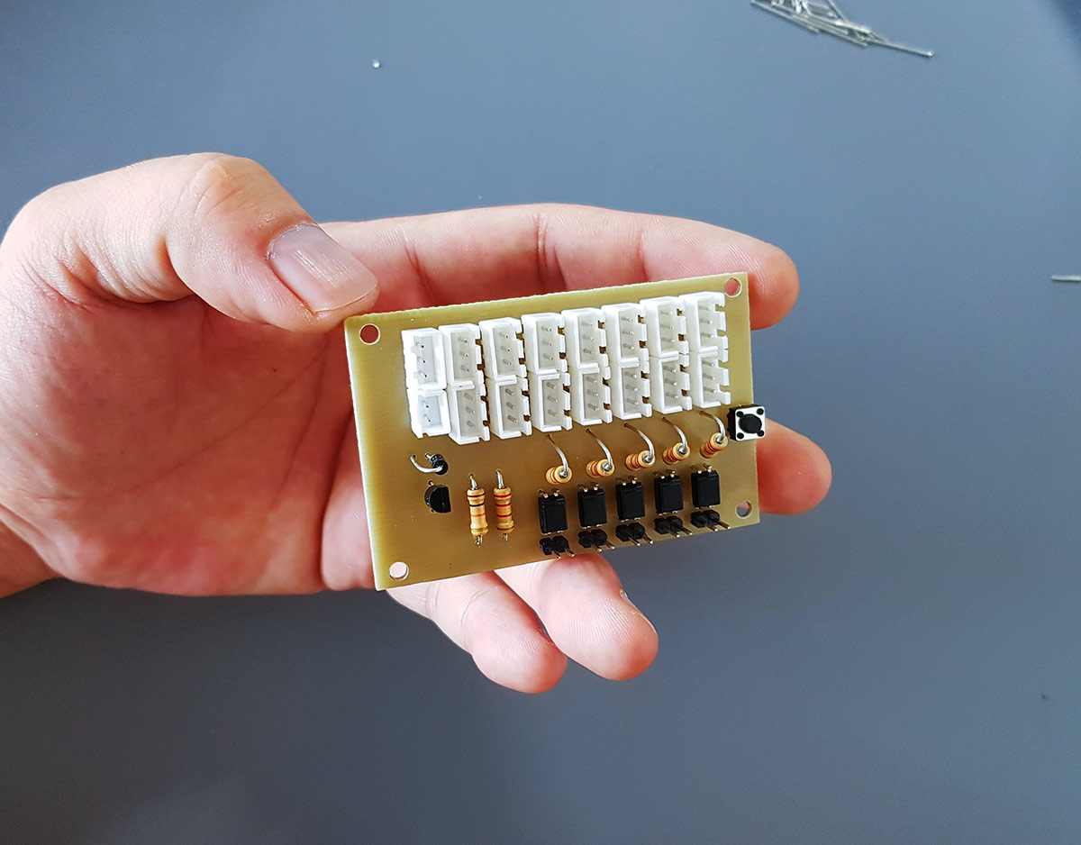
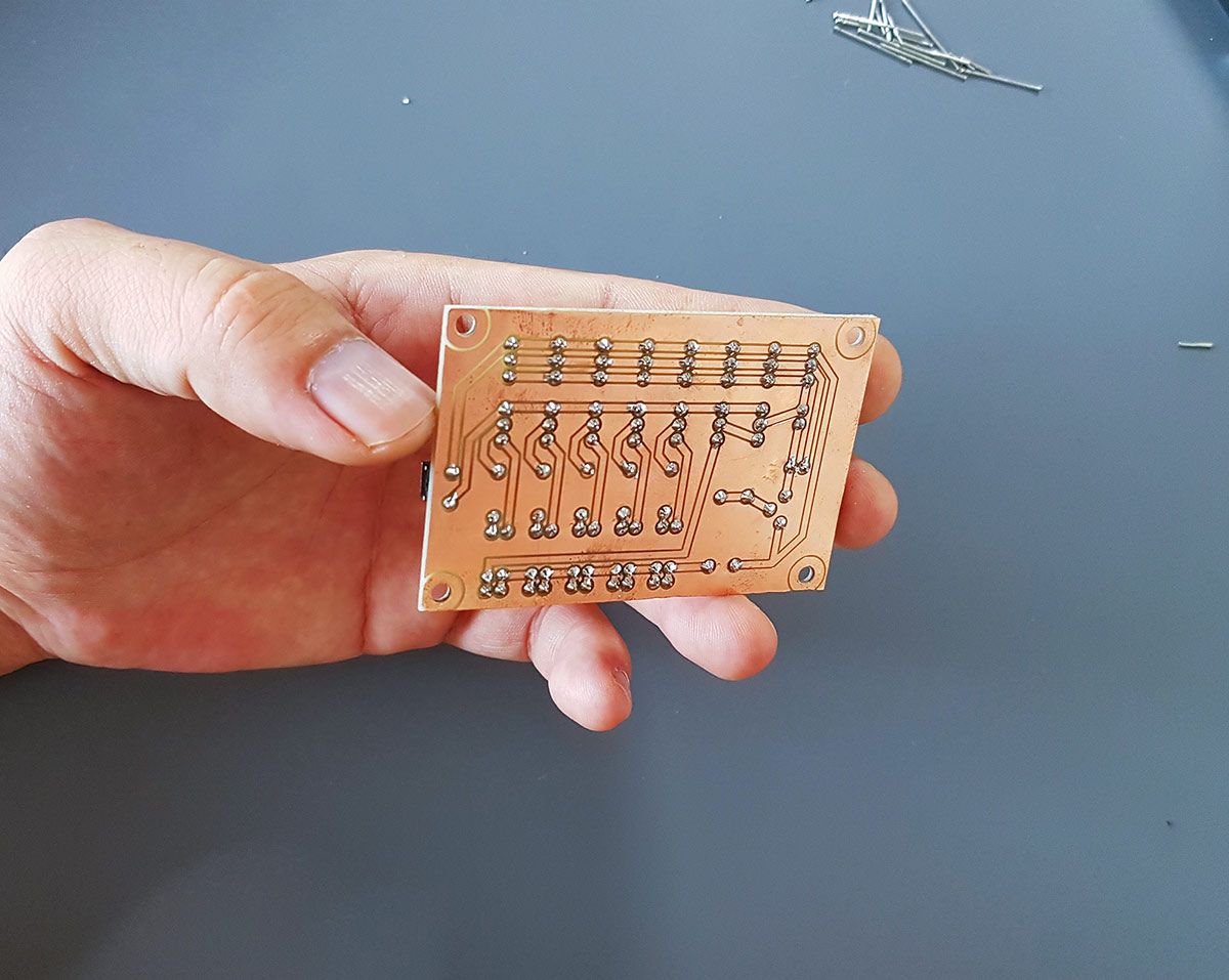
It might lack the pristine look of a factory-made board with a solder mask, but it’s sturdy and gets the job done. Here’s the final look at both the component side and the soldered traces.
Conclusion: The Pride of a Maker
Because the board was precision-cut on a CNC, it aligned perfectly with its mounting standoffs on the machine.
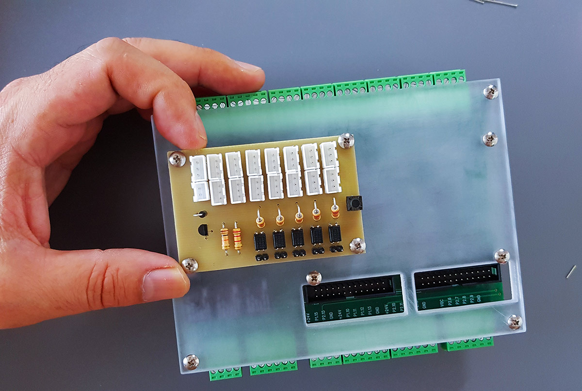
It’s just a simple, amateurish DIY board, but completing my very first CNC-milled PCB provided an immense sense of accomplishment. You don’t always need the fanciest commercial tools to build what you need.